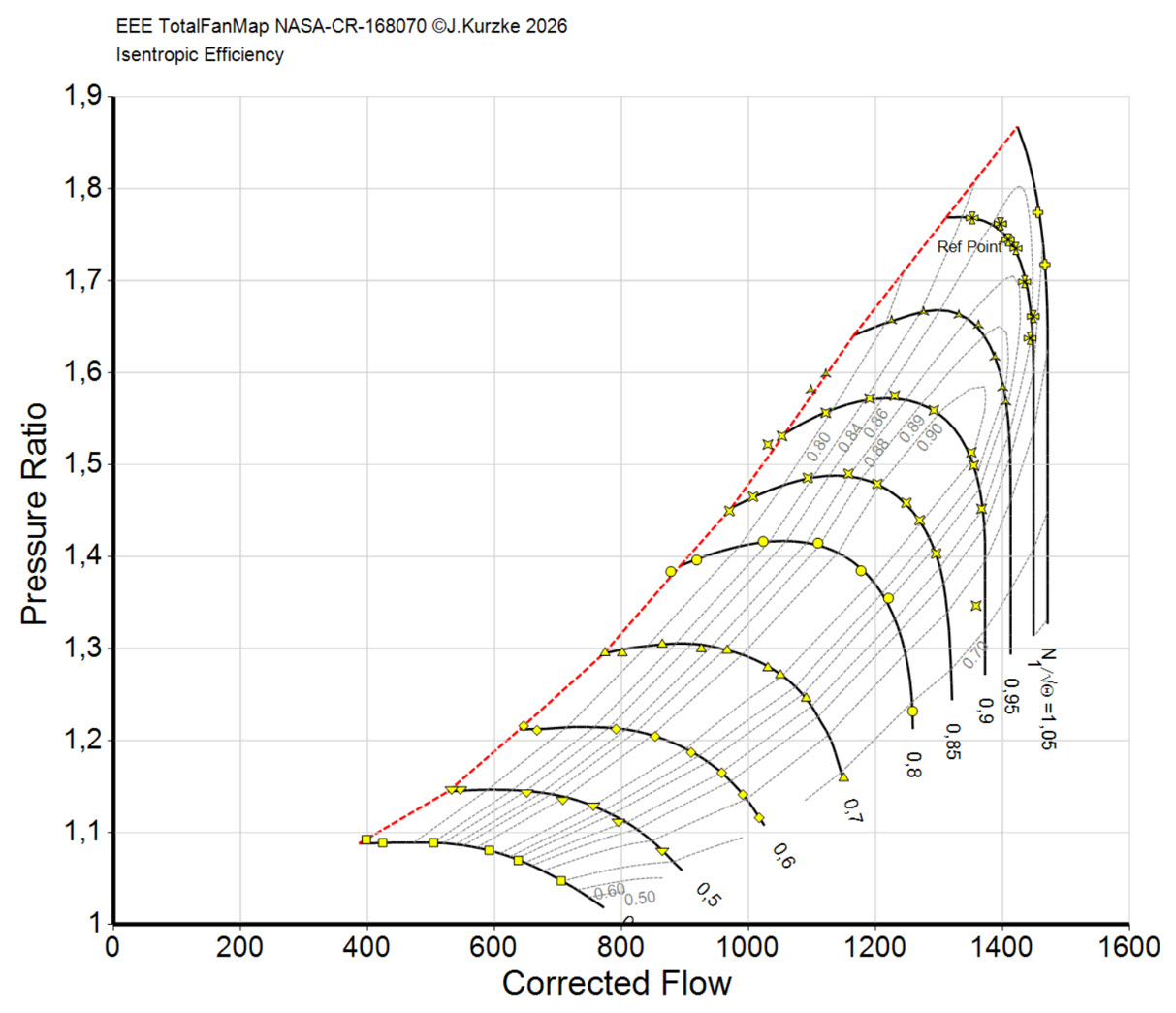
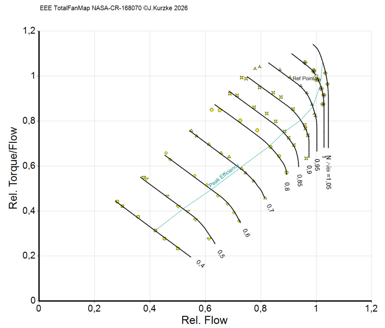
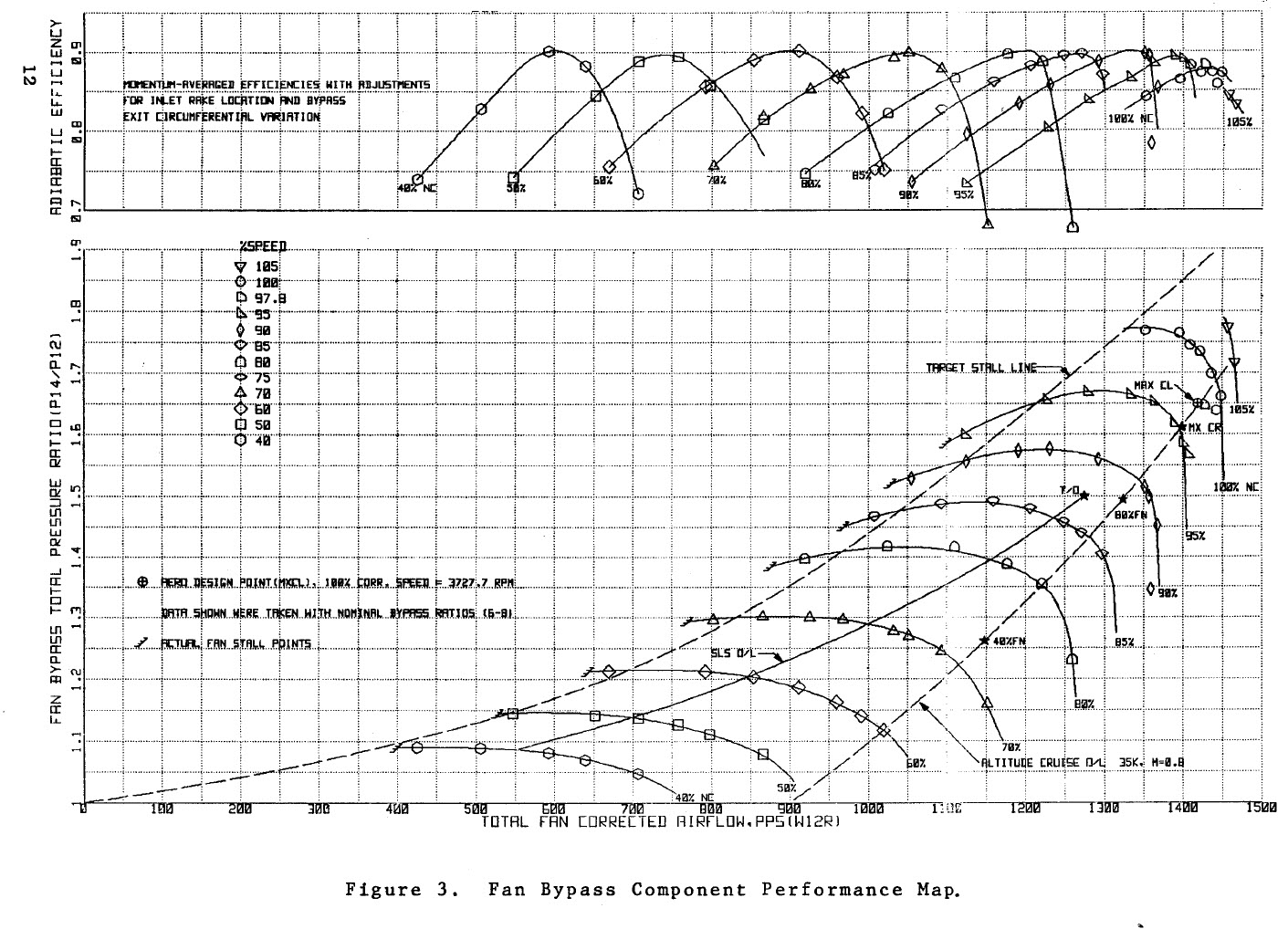
This Fan Bypass map is found in the NASA Contractor Report CR-168070, figure 3. Use this map together with the Fan Core map from figure 9.
About this fan
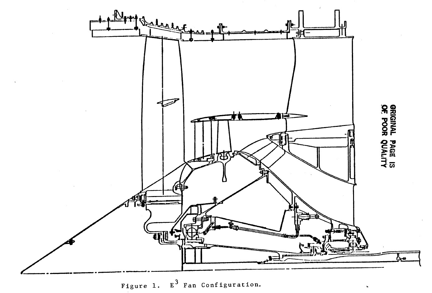
The fan configuration for the General Electric/NASA Energy Efficient Engine was selected following an extensive preliminary design study of alternate designs. As shown in the figure, the E³ fan configuration uses a quarter-stage booster to provide the required core supercharging. This type of design was chosen over a single-stage rotor with a higher tip speed and a more highly loaded hub because of its higher core-stream efficiency potential and its easier growth path for future engine development. The fan bypass stream also has a higher efficiency potential by reason of the lower fan speed.
Design Data
| Mass Flow [kg/s] | 644 |
| Bypass Pressure Ratio | 1.65 |
| Core Pressure Ratio | 1.67 |
| Bypass Ratio | 6.8 |
| Tip Speed [m/s] | 415 |
| Tip Diameter [m] | 2.108 |
| Inlet Radius Ratio | 0.342 |
Ref.:
Energy Efficient Engine
Fan and Quarter-Stage Component Performance Report
S.J. Cline, J.T. Kutney, Jr., P.H. Halter, T.J. Sullivan
General Electric
NASA CR-168070, 1983
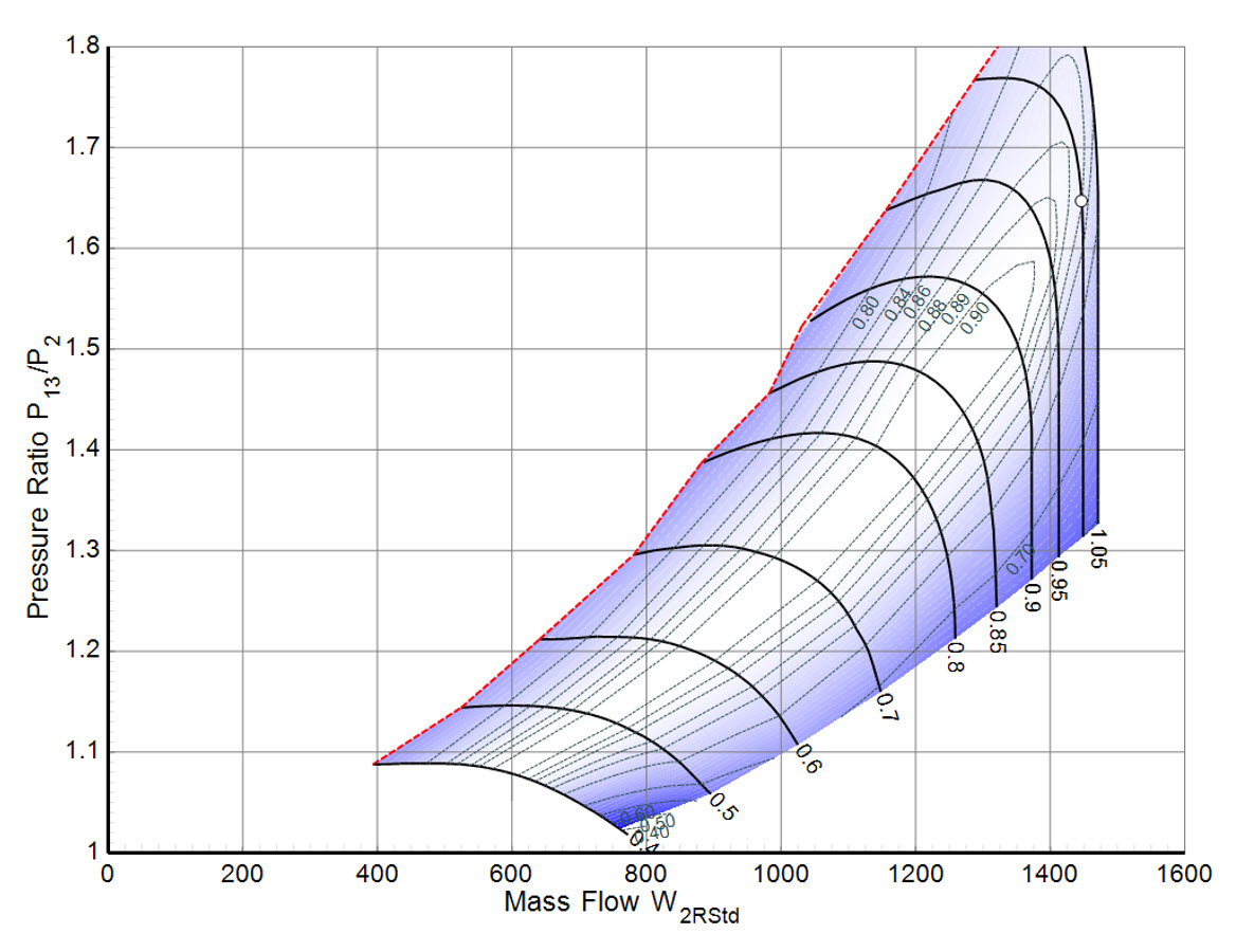
Figures of the measured data and the smooth map
Tables for use with performance programs
The map tables are available in four variants:
- EEE_Bypass_NASA-CR-168070BGasTurb.txt
- EEE_Bypass_NASA-CR-168070BNPSS.txt
- EEE_Bypass_NASA-CR-168070BExtndGasTurb.txt
- EEE_Bypass_NASA-CR-168070BExtndNPSS.txt
Note that the file extension must be changed to MAP after downloading if you want to use the map with GasTurb.
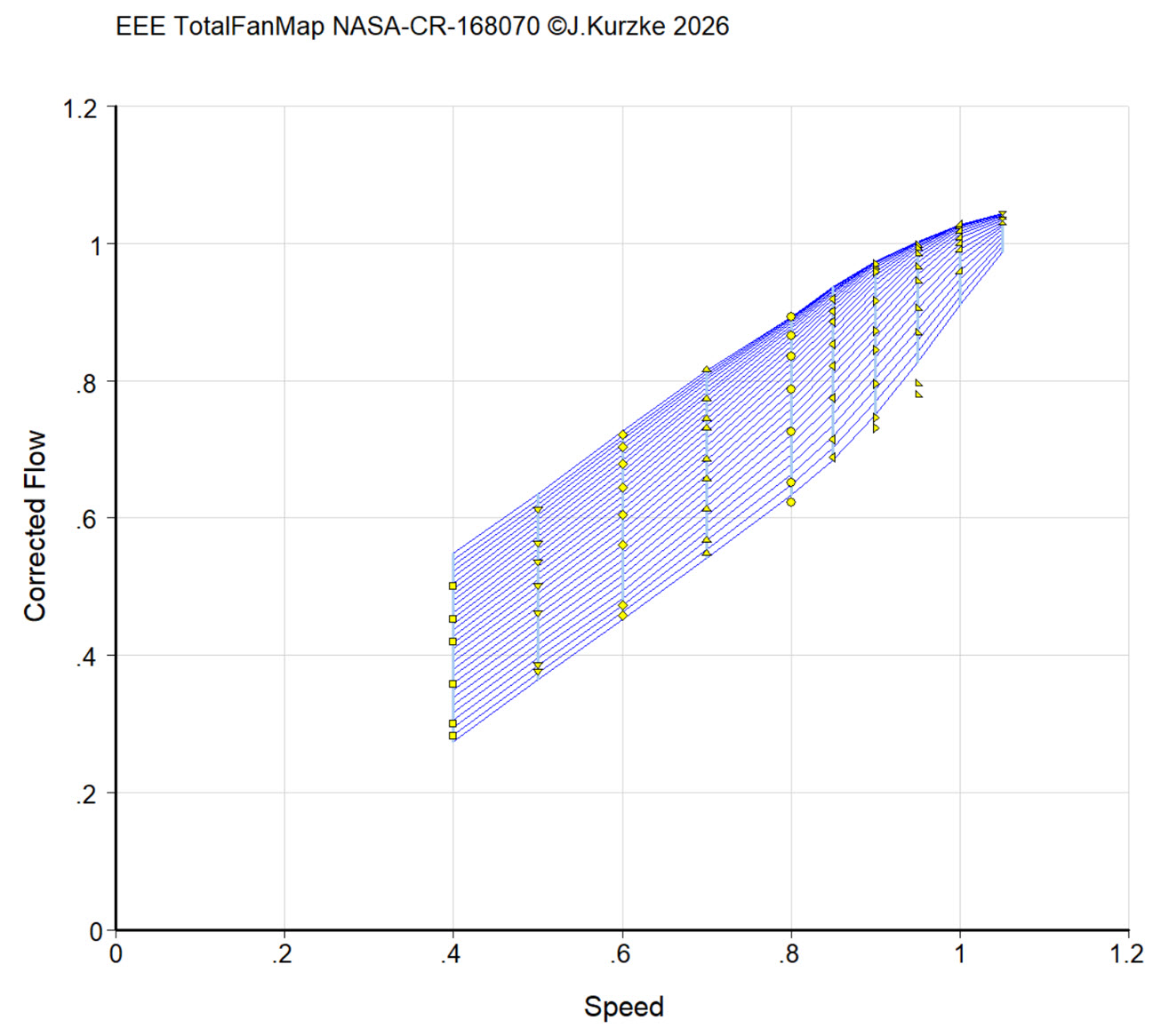
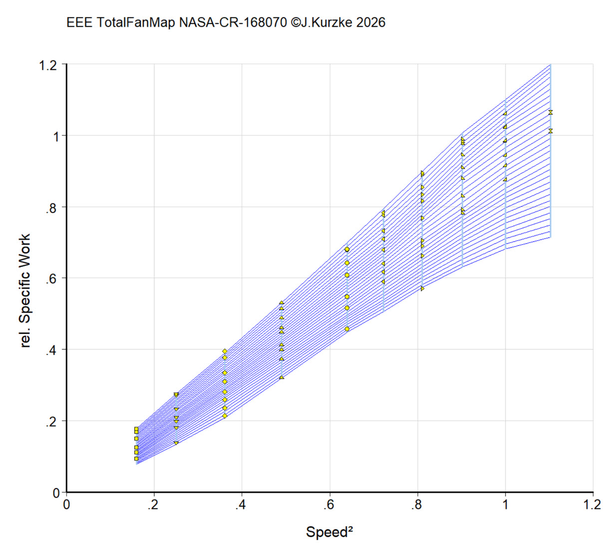
Additional figures from my experimental map smoothing program